Page 2 of 7

Re: Rug Warrior Pi: Build Blog (a PiDA bot)

PostPosted: Fri Aug 21, 2015 8:08 am
by mikronauts
You are welcome! I normally use two spacers, then the 18mm nylon spacers are at the correct height.

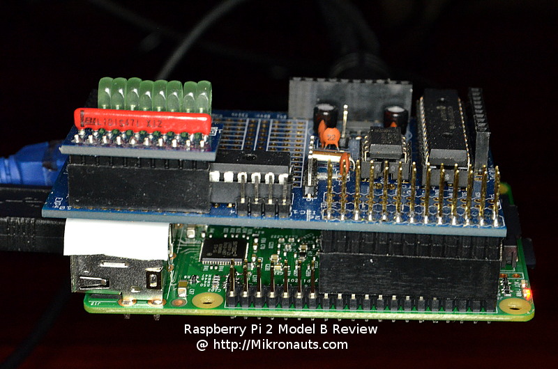
See this side way shot of the Pi Rtc Dio, and imagine it was Pi Droid Alpha... note how the stacking header is mounted.

Image

alanmcdonley wrote:
mikronauts wrote:The 26 pin stacking header should be assembled to PiDroidAlpha as shown on p.15 of the assembly manual


Good catch - thanks.

I cannot tell from the manual pic or words - how many 26 pin spacers under the board?

Alan

Re: Rug Warrior Pi moved his head and more

PostPosted: Wed Aug 26, 2015 4:32 pm
by alanmcdonley
My robot is coming together a little more every week. This week I finished assembling the Pi Droid Alpha (about 3 hours), created a "servo power" tap between the four and two cell battery holders, and fired up the stack. (I had to rewire the four and two cell packs as well to put the two cells on top of the four cells. When it was just a six cell source it didn't matter if ground came off the two cell or the four cell holder, but now it matters.)

The tilt/pan servos worked very nicely, which actually only uses the servo headers, servo power selection, and GPIO connections, but all those had to be confirmed working.

I tested each voltage divider protected servo pin as an input.

I tested the ADC analog to digital conversion chip and analog header pins - all working great.

I tested the motor driver chip (with forced dir enable inputs) and saw the wheels turn, so that looks promising that the L293 is functioning.

The DIO function is awaiting the PDALib update.

Pretty exciting.

Re: Rug Warrior Pi: Build Blog (a PiDA bot)

PostPosted: Wed Aug 26, 2015 4:52 pm
by mikronauts
Glad to hear about the progress!

I am in the middle of something else, so I have not had time to test it, but here is the fixed library attached below.

After I get a chance to test it, I will upload it to the product page.

Re: Choosing PWM_freq for DC Motor control

PostPosted: Sat Aug 29, 2015 7:15 am
by alanmcdonley
Instead of figuring out my DIO issue, I have been analyzing the effect of PWM_frequency on the no load minimum drive to start turning for each of my bot's motors.

Code: Select all
# Empirical settings for minimum drive to turn each wheel
# PWM_frequency dependent, PiDALib default is 490
# PWM_f   RMotorMinF   LMotorMinF
# 10000   215           185
# 490     83            73  <--
# 100     34            33
# 33      22            20


The RugWarriorPro designers, (Joseph Jones, Anita Flynn, Bruce Seiger - not necessarily in that order), chose a PWM frequency of 30 (32.77ms period). That choice may have been a convenient clock divider register available in the 6811 processor rather than motor optimization.

It is interesting to note that at lower PWM_frequency the motors start to respond at closer values of drive level. Since I don't have the DIO working, I haven't connected to the encoders to see how the speed derived bias acts.

It may be that I can drive slower with the higher PWM frequencies. It seems like at the minimum start drive level, the wheels are turning slower with higher PWM freq. If this proves out, that is a clear advantage for the default PWM frequency of 490 over the "original robot" PWM frequency of 30.

As long as I keep the drive above the minimum start level, I don't really hear the PWM frequency at 490. At 33 the startups can sound a little chunky.

For the time being at least I plan to:
a) leave the PDALib PWM_frequency at the default 490
b) use the start bias (RMotorMinF-LMotorMinF) to make both start at the same time
c) use the larger MotorMinF as the MotorsMinF for reliable start of both wheels.

Eventually I'll get fancy with closed loop speed control, but I need something simpler to get started with.

Itching to run around

PostPosted: Thu Sep 03, 2015 3:21 am
by alanmcdonley
Motor control fwd and backward works!

It was very tempting to switch from building to playing, and put my bot on the floor for its first autonomous actions.

I couldn't let it loose, blind and senseless.

Next are the 3 bumpers and 2 encoders signal wiring to the DIO banks, with pwr and ground for each. ( I have half of the power chain in place also- an electronic master power switch, and a 10a current sensor are mounted ready for testing also. )

Little by little.

Re: Rug Warrior Pi: Build Blog (a PiDA bot)

PostPosted: Thu Sep 03, 2015 8:14 am
by mikronauts
Thanks for the progress report! I am keeping a close eye on your build.

Which current sensor are you using? I use ACS712's.

Re: Current Sensor - ACS712

PostPosted: Thu Sep 03, 2015 1:57 pm
by alanmcdonley
mikronauts wrote:Which current sensor are you using? I use ACS712's.


That is what I mounted. I haven't looked at the values through the PiDA ADC yet - "on the list".

Alan

Re: Rug Warrior Pi: Build Blog (a PiDA bot)

PostPosted: Thu Sep 03, 2015 8:38 pm
by mikronauts
analogRead() returns a 10 bit result, which is 1024*Vin/Vcc

the +/- 5A version is calibrated to 0.185V/5V according to the data sheet, however it appears to be ratiometric depending on Vcc.

current = ((analogRead(ch)-512)*0.185)/5 .... in amps

current = ((analogRead(ch)-512)*0.185)*200 .... in milliamps

Re: Current Sensor - ACS712

PostPosted: Fri Sep 04, 2015 4:50 am
by alanmcdonley
mikronauts wrote:current = ((analogRead(ch)-512)*0.185)*200 .... in milliamps


I tried using:
Code: Select all
def current_sense():   # Sensor states 0.185V/A
    ACS712PIN = 7  # Current sensor is on pin 7 (0..7) of the MCP3008
    pin_value = PDALib.analogRead(ACS712PIN)
    # Bill Henning: ((pin_value-512)*0.185) *200 in milliamps
    current_now = ((pin_value-512)*5.0/512)*1000
    return [current_now, pin_value]


and get readings from 512 to 516 (0 to 40 ma with my formula) when no voltage/no current and with voltage/negligible draw of a 5V switching supply with no load.

I guess I need some known resistor loads to verify this thing.

Re: Current Sensor - ACS712

PostPosted: Fri Sep 04, 2015 7:29 am
by mikronauts
As I recall, the ACS712 data sheet says it is +/- 1.5% accurate at best.

512 *.015 = 7.68

So 512-516 looks like a valid result. You could try a simple filter, something like

LastSample = NewSample
NextSample = 0.75*LastSample + 0.25*NewCurrentReading

alanmcdonley wrote:
mikronauts wrote:current = ((analogRead(ch)-512)*0.185)*200 .... in milliamps


and get readings from 512 to 516 (0 to 40 ma with my formula) when no voltage/no current and with voltage/negligible draw of a 5V switching supply with no load.

I guess I need some known resistor loads to verify this thing.